Ignition Control: IGN Modes / Auto Power On
Brief Overview
Several computers have built in ignition control, and others can have it added. The quickest and simplest way to think of an ignition control function is when you shut your car off with the radio on. The windows and radio will operate for a set amount of time after the engine is powered off. Industrial computer ignition control has many more combinations of functions. More technical information follows.
Do not confuse ignition control with remote on off which is a cable that extends the reach of the power button and serves only in that capacity.
The ignition power control switch features multiple modes for pre and post ignition settings. Please refer to the section in the operators manual Ignition Power Control for details. Use a flathead screwdriver to adjust the position of the ignition power control switch.
The ignition power control module for in-vehicle applications is an MCU-based implementation that monitors the ignition signal and reacts to turn on/off the system according to predefined on/off delay. Its built-in algorithm supports other features such as ultra-low power standby, battery-low protection, system hard-off, etc. In this section, we will illustrate the principle of ignition power control and operation modes
Principles of Ignition Power Control
The basic concept of ignition power control module is to control the timing correlation between ignition signal and system power status. A typical timing correlation is described in the following diagram.
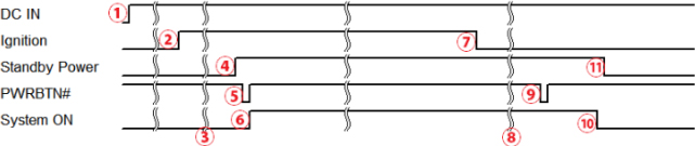
- When DC power is supplied to the system, the MCU starts to periodically detect ignition signal. Note that only MCU is working at this moment and the overall power consumption is less than 2 mW.
- Ignition signal is active (both 12VDC and 24VDC ignition signals are accepted).
- MCU starts to count a pre-defined power-on delay.
- Once the power-on delay expired, MCU turns on necessary standby power for the system (3.3VSB & 5VSB).
- A PWRBTN# pulse is then issued to turn on the system (equivalent to one pressing the power button on the front panel).
- The system is booting and becomes operational.
- After a brief moment, the ignition signal becomes inactive.
- MCU starts to count a pre-defined power-off delay.
- Once the power-off delay expires, another PWRBTN# pulse is issued to perform a soft-off for the system (ex. a normal shutdown process for Windows system).
- The system is completely shut down.
- As MCU detects system is off, it turns off the standby power for the system, and operates in low power mode again (< 2mW power consumption).
Additional Features of Ignition Power Control
In addition to the typical timing correlation, the ignition power control module offers additional features to provide additional reliability for in-vehicle applications.
- Low battery detection: The ignition power control module continuously monitors the voltage of DC input when the system is operational. If input voltage is less than 9V (for 12VDC input) or less than 18V (for 24VDC input) over a 60-second duration, it will shut down the system automatically.
- Guarded power-on/ power-off delay duration: If ignition signal goes inactive during the power-on delay duration, the ignition power control module will cancel the power-on delay process and go back to idle status. Likewise, if ignition signal goes active during the power-off delay duration, the ignition power control module will cancel the power-off delay process and keep the system running.
- System hard-off: In some cases, the system may fail to shutdown via a soft-off operation due to system/ application halts. The ignition power control module offers a mechanism called “hard-off” to handle this unexpected condition. By detecting the system status, it can determine whether the system is shutting down normally. If not, the ignition power control module will force cut-off the system power 10 minutes after the power-off delay duration.
- Smart off-delay: The ignition power control module offers two modes (mode 13 & mode 14) which have exceptionally long power-off delay duration for applications require additional off-line time to process after the vehicle has stopped. In these two modes, the ignition power control module will automatically detect the system status during the power-off delay duration. If the system has shutdown (by the application software) prior to power-off delay expiring, it will cut off the system power immediately to prevent further battery consumption.
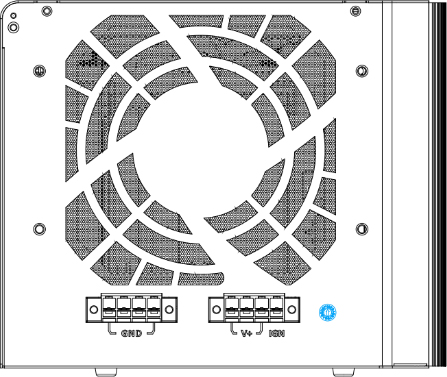
Wiring Ignition Control
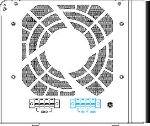
To have ignition power control for in-vehicle usage, you need to supply IGN signal to the system. The IGN input is on the 4-pin pluggable terminal block (shared with DC power input). Below is the typical wiring configuration for in-vehicle applications. 1. Connect car Battery+ line (12V for sedan, 24V for bus/truck) to V+. 2. Connect car Batter-/ GND line to GND. 3. Connect ACC line to IGN.