
AIMB-789: LGA1851 Intel Core Ultra 9/7/5 ATX with HDMI/VGA, DDR5, USB 3.2, 6 COMs
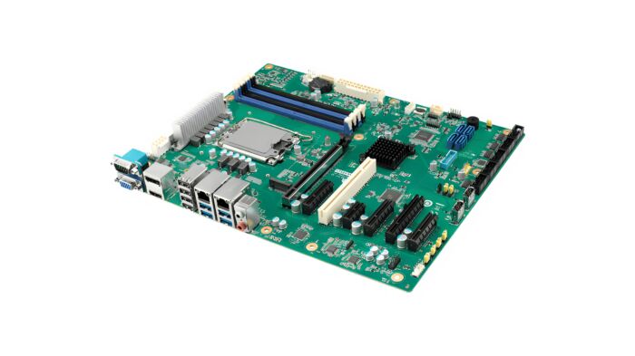
AIMB-789LGA1851 Intel Core Ultra (Series 2) ATX Motherboard with DP/HDMI/VGA, DDR5, USB 3.2, and M.2.
- Intel Core Ultra 9/7/5 processor with Q870 chipset
- Four DIMM sockets up to 192GB DDR5 5600
- Triple display DP/HDMI/VGA and dual GbE LAN
- M.2, SATA RAID 0, 1, 5, 10, USB 3.2 Gen 2
- iBMC remote out-of-band power management on DeviceOn
- Legacy platform is not supported
- dTPM 2.0 module is required to enable Intel vPro and TPM
- Intel Platform Trust Technology (Intel PTT) ready for Win 11

Frequently Asked Questions
The AIMB-789 uses an LGA1851 socket and supports Intel® Core™ Ultra (Series 2) desktop processors, including Ultra 9 285/285T, Ultra 7 265/265T, Ultra 5 245/245T, and Ultra 5 225/225T. The chipset is Intel® Q870. Legacy platforms are not supported.
The board has four 288-pin DIMM sockets supporting dual-channel, non-ECC DDR5 5600 (the startup manual lists DDR5 4400 support), with a maximum capacity of 192 GB. Memory configuration must follow Intel's guidelines: for a single DIMM, install it in slot DIMMB2; for two DIMMs, use DIMMB2 and DIMMA2. Installing three DIMMs is not permitted.
The board provides triple display support via one VGA port (up to 1920 x 1200 @ 60 Hz), one HDMI port (up to 3840 x 2160 @ 30 Hz), and one DisplayPort (up to 4096 x 2304 @ 60 Hz). Graphics are driven by the CPU-integrated Intel Xe LPG graphics controller.
The board has 4 SATA 3.0 channels supporting data rates up to 600 MB/s with AHCI, and supports SATA RAID 0, 1, 5, and 10. It also includes an M.2 M-Key 2280 socket supporting PCIe x4 Gen 5 storage devices (labeled NVME1). A second M.2 socket, NVME2, is present only on the AIMB-789-1 version.
The board provides six serial ports: COM1, COM2, and COM4 through COM6 are RS-232 (COM1 is a rear DB-9 connector; the others are via headers). COM3 is configurable as RS-232/422/485 via a 9-pin header, with BIOS menu options for mode selection.
Rear I/O includes 8 USB ports: 2 x USB 3.2 Gen 2, 2 x USB 3.2 Gen 1, and 4 x USB 2.0. Internally, there are 2 x USB 3.2 Gen 1 and 2 x USB 2.0 via headers, plus 2 x USB 2.0 internal Type-A connectors.
The operating temperature is 0 ~ 60 °C (32 ~ 140 °F), depending on CPU speed and thermal solution. Non-operating (storage) temperature is -40 ~ 85 °C (-40 ~ 185 °F). Humidity tolerance is 40 °C @ 95% RH and 60 °C @ 95% RH, both non-condensing.
With an Intel Core Ultra 65W CPU and DDR5 32 GB x 4 installed, maximum power draw is +3.3V at 7.35A, +5V at 3.45A, +12V at 0.21A, +5Vsb at 0.23A, and -12V at 0.06A. The board uses an ATX 24-pin main power connector (EATXPWR1) and a 12V auxiliary power connector for the CPU (ATX12V1/ATX12V2).
The AIMB-789 measures 304.8 x 244 mm (12" x 9.6") and weighs 0.7 kg (1.54 lb). This is a standard ATX form factor board.
The board offers one PCIe x16 Gen 5 slot, one PCIe x8 slot (Gen 4, x4 link), three PCIe x4 Gen 4 slots, one PCIe x1 Gen 4 slot, and one PCI slot. Note that the AIMB-789 does not support PCI riser cards.
How-to Guides
- Power off the system and disconnect all power sources.
- If installing a single DIMM, place it in slot
DIMMB2. - If installing two DIMMs, use slots
DIMMB2andDIMMA2. - Do not install three DIMMs in any configuration — this is not permitted.
- For four DIMMs, populate
DIMMA1,DIMMA2,DIMMB1, andDIMMB2. - Reconnect power and boot the system to verify memory is recognized.
- Power off the system and disconnect all power sources.
- Locate the M.2 M-Key 2280 socket labeled
NVME1on the board. - On the AIMB-789-1 version, a second M.2 socket
NVME2is also available. - Insert a PCIe x4 Gen 5 M-Key 2280 type M.2 storage device into the socket at an angle, then press down and secure with the retention screw.
- Reassemble the system and power on to verify the drive is detected.
- Locate the COM3 header on the board, which supports RS-232/422/485.
- Enter the system BIOS setup menu.
- Navigate to the BIOS menu options for COM3 mode selection.
- Select the desired serial mode (RS-232, RS-422, or RS-485).
- Save changes and exit BIOS setup.
- Power off the system and disconnect the power cord.
- Locate the
JCMOS1jumper on the board. - The default position (pins 1-2 closed) keeps CMOS data.
- Move the jumper to pins 2-3 to clear CMOS data.
- Wait a few seconds, then return the jumper to the default 1-2 position.
- Reconnect power and boot the system.
- Power off the system and disconnect the power cord.
- Locate the
PSON1jumper on the board. - Set pins 1-2 closed for AT mode.
- Set pins 2-3 closed for ATX mode (this is the default setting).
- Reconnect power and boot the system to confirm the selected mode.
LGA1851 Intel Core Ultra (Series 2) ATX Motherboard with DP/HDMI/VGA, DDR5, USB 3.2, and M.2.
| Product Available On | Jun 2, 2030 |
|---|---|
| Manufacturer | Advantech |
| Short Description | LGA1851 Intel Core Ultra (Series 2) ATX Motherboard with DP/HDMI/VGA, DDR5, USB 3.2, and M.2. |
| BIOS | AMI 256 bytes SPI Flash |
| CPU | Socket: LGA 1851 |
| Frequency | Ultra 9 285: 2.5GHz |
| L3 Cache | Ultra 9 285: 36MB |
| Memory | Dual Channel(non-ECC) DDR5 5600 |
| Network (LAN) | Interface: LAN1: 10/100/1000 Mbps; LAN2: 10/100/1000 Controller: GbE LAN1: Intel I219-LM (PHY); GbE LAN2: Intel I210-AT Connector: RJ-45 |
| I/O | Rear IO Internal Connectors |
| Expansion Slots | PCI: 1 |
| Watchdog TImer | Output: System reset |
| Humidity | Operating: 40 °C @ 95% RH Non-condensing |
| Operating Temperature | Operating: 0 ~ 60 °C (32 ~ 140 °F), depends on CPU speed and system thermal solution |
| Power Input Voltage | Power On: Intel Core Ultra 65W, DDR5 32 GB x 4 |
| Dimension | 304.8 x 244 mm (12" x 9.6") |