
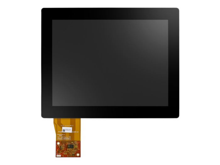
IDK-1110 Series 10.4" SVGA/XGA Industrial Display Kit with Touch Solution
IDK-1110P-50XGB1Main Features:
- 10.4" LCD supports 800 x 600 and 1024 x 768 resolution
- 4-wire resistive and projected capacitive touch solutions
- LVDS signal interface
- LED driver board built in
- Touch controller included (USB)
- Anti-Reflection surface treatment (customized solution)
- Optical bonding (customized solution)

Frequently Asked Questions
The IDK-1110R-series is a 10.4 inch color TFT LCD module with a screen format of SVGA, 800(H) x 600(V) pixels. It supports 16.2M colors (RGB 8-bits) or 262k colors (RGB 6-bits). The active area is 211.2mm (H) x 158.4mm (V), with a pixel pitch of 0.264mm x 0.264mm.
The absolute maximum ratings list an operating temperature range of -10°C to +60°C, with operating humidity of 20% to 90% RH (no condensation, max wet-bulb 39°C). Storage temperature is -30°C to +70°C (for the 40SVA1E variant) or -20°C to +70°C (for the 23SVA1E variant), with storage humidity of 10% to 90% RH.
The LCD module's nominal logic/drive input voltage (VDD) is 3.3V (typical), with a rated range of 3.0V to 3.6V. Typical power consumption is 4.8W (for IDK-1110R-40SVA1E) or 3.5W (for IDK-1110R-23SVA1E). The LED backlight unit requires 10.8V to 12.6V input (12V typical) on a separate connector, with typical power consumption of 3.8W (40SVA1E) or 1.44W (23SVA1E) at 100% PWM duty.
The panel uses an LVDS (Low-Voltage Differential Signaling) interface on connector CN1, a 20-pin connector (STM-MSB24013P20HA or compatible). It supports both 6-bit and 8-bit LVDS data input, selectable via the SEL68 pin (high = 8-bit, low/NC = 6-bit).
Yes. The IDK-1110R-series includes a 4-wire resistive touch screen solution. The touch panel connects via a Touch Screen Connector (JP2), a 4-pin FFC/FPC connector, and is driven by the Advantech ETM-RES05C touch controller board.
The Advantech ETM-RES05C touch controller communicates with the host PC through a combo USB and RS-232 connector (JP1). It supports Windows 2000, Vista, XP, 7, Windows CE 5.0/6.0/7.0, Windows NT4, Linux, DOS, and QNX (specific OS support varies between the RS-232 and USB interfaces).
The touch controller board operates from -25°C to +85°C and has the same storage range. Reliability is rated at an MTBF of 200,000 hours. It carries RoHS certification and FCC-B and CE regulatory approvals.
The touch controller provides 2,048 x 2,048 touch resolution with a maximum response time of 20ms. Report rate is up to 180 points/sec over RS-232 or up to 200 points/sec over USB.
For the IDK-1110R-40SVA1E variant: module size is 243mm (H) x 184mm (V) x 10.6mm (D), weighing 530g. For the IDK-1110R-23SVA1E variant: module size is 236mm (H) x 176.9mm (V) x 8.3mm (D), weighing 470g.
How-to Guides
- Ensure VDD power is off before inserting or disconnecting any input connector.
- Connect the LVDS signal cable to CN1 (a 20-pin STM-MSB24013P20HA or compatible connector), matching pin assignments including VDD, GND, RxIN0- through RxIN3+, RxCLKIN, DPS, and SEL68 as required for your 6-bit or 8-bit data format.
- Connect the LED backlight driver cable to CN2, wiring Pin1 (VCC, 12V input), Pin2 (GND), Pin3 (On/Off, 5V-ON/0V-OFF), and Pin4 (Dimming/PWM) as needed.
- Follow the documented power ON/OFF sequence timing (T1-T13) to avoid abnormal display function.
- Do not rotate or tilt the interface connector during insertion or removal, and do not bend or twist the module after installation into an enclosure.
- Identify pin 20 (SEL68) on the LVDS connector (CN1).
- Set SEL68 to Low or leave it NC (not connected) to select 6-bit LVDS input.
- Set SEL68 to High to select 8-bit LVDS input.
- When using 6-bit mode, note that RxIN3 signals are not connected (NC).
- Confirm the RGB bit mapping matches your host graphics controller output (MSB/LSB assignments differ between 6-bit and 8-bit modes).
- Connect the touch screen panel to the JP2 connector on the ETM-RES05C touch controller board (a 4-pin FFC/FPC connector: YB, XL, YT, XR).
- Connect the host PC to the JP1 combo interface connector using either the USB pins (Ground, USB Power, Ground, D+, D-) or the RS-232 pins (Ground, Power, Ground, TxD, RxD).
- Note that if USB is connected, the controller communicates over USB and will not use the serial port simultaneously.
- For RS-232 communication, configure the host serial port for 9600 baud, no parity, 8 data bits, 1 stop bit (N, 8, 1, 9600).
- Install the appropriate touch panel driver for your operating system (Windows 2000/Vista/XP/7, Windows CE 5.0/6.0/7.0, Windows NT4, Linux, DOS, or QNX) so the touch input emulates mouse functions.
- Avoid scratching the front polarizer, which is easily damaged.
- Always turn off the power supply before inserting or disconnecting the input connector.
- Wipe off any water immediately to prevent discoloration or spotting.
- Clean a soiled panel surface only with absorbent cotton or other soft cloth.
- Handle the module carefully since the glass panel can break or crack if dropped or bumped.
- Observe standard ESD precautions (grounding) when handling, since CMOS LSI components are used in the module.
- Do not press on the reflector sheet at the back of the module in any direction.
- After mounting the module into an enclosure, ensure no bending or twisting forces are applied to it from the enclosure design.
| Manufacturer | Advantech |
|---|---|
| Short Description | 10.4" SVGA/XGA industrial display kit with touch solution. |
| Display Type | LED |
| Display Size | 10.4" |
| Max Resolution | 1024 x 768, XGA |
| Max Colors | 16.2M |
| Luminance | 500nits |
| Viewing Angle | 176/176 |
| Backlight Lifetime | 50,000 Hours |
| Contrast Ratio | 1000 : 1 |
| Humidity | 90% @ 39°C, non-condensing |
| Operating Temperature | -20°C ~ 70°C |
| Storage Temperature | -30°C ~ 80°C |
| Weight | 500 g |
| Dimension | 251.03mm x 202.42mm x 11.32 mm |