
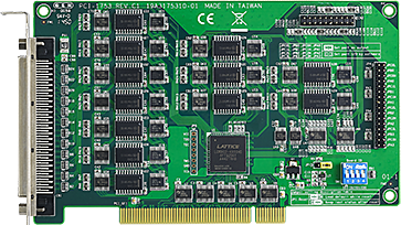
PCI-1753-CE 96ch TTL Digital I/O Card
PCI-1753-CEMain Features:
- Up to 192 (96 + 96) TTL digital I/O lines
- Emulates mode 0 of 8255 PPI
- Buffered circuits for higher driving capacity than 8255
- Multiple-source interrupt handling
- Interrupt output pin for simultaneously triggering external devices with the interrupt
- Output status read-back

Frequently Asked Questions
The PCI-1753 provides 96 TTL digital I/O lines, divided into twelve 8-bit ports: A0, B0, C0, A1, B1, C1, A2, B2, C2, A3, B3, and C3. Each port can be configured as input or output via software. Using the PCI-1753E extension board, the total can be expanded to 192 digital I/O lines.
The card uses one 100-pin SCSI female connector for all digital I/O lines.
Input signal levels: logic 0 is 0.8 V max, logic 1 is 2.0 V min. Output signal levels: logic 0 is 0.8 V max at +24 mA (sink), logic 1 is 2.0 V min at -15 mA (source), per the datasheet. The user's manual lists slightly different output figures: logic 0 at 0.44 V max @ 24 mA (sink) and logic 1 at 3.76 V min @ 24 mA (source).
The card draws +5 V at a typical 400 mA and a maximum of 2.7 A.
Operating temperature is 0 to 60°C (32 to 140°F). Storage temperature is -20 to 70°C (-4 to 158°F). Storage/operating humidity is 5 to 95% RH, non-condensing.
Yes. It supports multiple-source interrupt handling with 4 interrupt inputs (PC00, PC10, PC20, PC30), plus dedicated "pattern match" interrupt function on port A0 and "change of state" interrupt function on port B0. An interrupt output pin can also simultaneously trigger external devices.
Yes. Each digital input channel accepts either 0~5 V wet contact or dry contact inputs, allowing the channel to respond to changes in external circuitry even when no voltage is present.
The card can keep its output settings and values after a hot reset, depending on jumper JP1. If JP1 is enabled, ports return to the state held just prior to the reset. If disabled, ports return to a default state (input, high for software-set ports, or output-low for jumper-set ports). Note that a complete power disconnection (not just a hot reset) always clears this memorized state.
The card measures 175 x 100 mm (6.9" x 3.9").
Yes. The PCI-1753E extension board can be added to double the I/O count from 96 to 192 digital I/O lines. It connects to the PCI-1753 via a 10-cm 20-pin flat cable and shares the PCI-1753's interface controller, so it does not need its own PCI controller.
How-to Guides
- Turn off the computer and any connected accessories, then disconnect the power cord and other cables.
- Remove the computer's cover.
- Select an empty 5 V PCI slot. If installing the PCI-1753E extension as well, find two adjacent 5 V PCI slots.
- Remove the screw securing the expansion slot cover and save it for the retaining bracket.
- Align the card's gold edge connector with the expansion slot and press it in firmly until it is fully seated.
- If using the PCI-1753E, repeat the seating step for it, then connect the PCI-1753 and PCI-1753E using the supplied 10-cm 20-pin flat cable, matching the first pin marks on each connector.
- Secure the card(s) by screwing the mounting bracket to the computer's back panel.
- Attach any accessories such as the 100-pin cable or wiring terminal board.
- Replace the computer cover and reconnect the cables.
- Turn the computer power on.
- Locate the jumpers JPA0, JPB0, JPC0L, JPC0H, JPA1, JPB1, JPC1L, JPC1H, JPA2, JPB2, JPC2L, JPC2H, JPA3, JPB3, JPC3L, JPC3H on the card.
- Leave a port's jumper open (not shorted) to make that port software-configurable as input or output.
- Short a port's jumper to fix that port as an output port; it can no longer be set as input by software.
- Note the initial state: software-configurable ports default to input, logic 1 (high); jumper-set output ports default to logic 0 (low) at startup, unless JP1 changes this behavior.
- Locate jumper JP1 on the card.
- Short the lower two pins of JP1 to enable reset protection: after a hot reset, all ports (software-set or jumper-set) return to the state and output values they held just prior to the reset.
- Short the upper two pins of JP1 to disable reset protection: after reset or power-off, ports return to their default state (input high for software-set ports, output low for jumper-set ports).
- Note that a complete loss of power to the card always clears this memorized state, regardless of the JP1 setting.
- Decide which input channels of port A0 you want to monitor for pattern matching.
- Write to the Pattern Match Enable Register (Base+24, or Base+56 for the PCI-1753E) to enable the desired channels.
- Write the target logic pattern for the enabled channels to the Pattern Match Value Register (Base+20, or Base+52 for the PCI-1753E).
- Enable the pattern match function for port A0 by writing a 1 to bit 0 (M1) of the Interrupt Control Register (Base+16, or Base+48 for the PCI-1753E).
- When the enabled channels' states match the pre-set pattern, the card generates an interrupt to the system.
- Decide which channels of port B0 you want to monitor for state changes.
- Write to the Change of State Enable Register (Base+28, or Base+60 for the PCI-1753E) to enable the desired channels.
- Enable the change of state function for port B0 by writing a 1 to bit 2 (M2) of the Interrupt Control Register (Base+16, or Base+48 for the PCI-1753E).
- When any enabled channel changes state, the card generates an interrupt to the system.
| Manufacturer | Advantech |
|---|
-
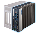 MIC-7500 Advantech MIC-7500 Intel 6th Generation Core i Processor Compact Fanless System
Starting at $1,480.00
- MIC-7500 Advantech MIC-7500 Intel 6th Generation Core i Processor Compact Fanless System
Starting at $1,480.00