
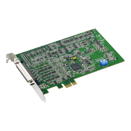
PCIE-1810-AE 16ch, 12bit, 800kS/s PCIE Multifunction
PCIE-1810-AEMain Features:
- 16 analog inputs, up to 800 KS/s, 12-bit resolution
- 2 analog outputs, up to 500 KS/s, 12-bit resolution
- Support for digital trigger and analog trigger (AI only)
- 24 programmable digital I/O linesƒƒ Two 32-bit programmable counter/
- Two 32-bit programmable counter/timers
- Onboard FIFO memory ( 4 K samples)
- Automatic channel/ gain scanning
- Support for Microsoft Windows 7/XP

Frequently Asked Questions
The card provides 16 single-ended or 8 differential analog input channels with 12-bit resolution, up to 800 kS/s on a single channel or 500 kS/s across multiple channels. It also provides 2 analog output channels with 12-bit resolution and an output rate up to 500 kS/s. Input ranges are software-programmable from ±10V down to ±0.625V (bipolar) or 0~10V down to 0~1.25V (unipolar), depending on the selected gain.
The PCIE-1810 has 24 programmable digital I/O lines that are 5V/TTL compatible, with sink capability of 15 mA @ 0.8V and source capability of 15 mA @ 2.0V. It also includes two independent 32-bit counter/timers with a maximum input frequency of 10 MHz, supporting event counting, frequency measurement, pulse width measurement, and pulse/PWM output generation.
The card draws its power from the PCI Express bus. Typical consumption is 3.3V @ 488 mA and 12V @ 112 mA. Maximum consumption is 3.3V @ 2.25A and 12V @ 390 mA.
Operating temperature is 0 to 60°C (32 to 140°F), per IEC 60068-2-1,2. Storage temperature is -40 to 70°C (-40 to 158°F). Storage humidity is 5~95% RH non-condensing, and operating relative humidity is 5~85% RH non-condensing, per IEC 68-1,-2,-3.
The card is RoHS compliant (2002/95/EC) and CE/FCC certified. It has passed the CE test for environmental specifications when shielded cables are used for external wiring.
The PCIE-1810 is a PCI Express x1 card measuring 167 x 100 mm (6.6" x 3.9"). It uses a 68-pin SCSI female I/O connector for field wiring.
The PCIE-1810 ships with Advantech DAQNavi device drivers and SDK on a companion DVD-ROM, supporting Windows XP/Vista/7. The drivers integrate with development tools such as Visual Studio .NET, Visual C++, Visual Basic, Delphi, and C++ Builder. A LabVIEW driver is also available.
The two D/A channels can use an internal precision reference to generate 0~5V, 0~10V, ±5V, or ±10V output, or an external reference for other ranges (0 to +x V or ±x V, where -10 ≤ x ≤ 10). The maximum reference input voltage is ±10V and maximum output scaling is ±10V. Loading current should not exceed 5 mA.
Available accessories include the PCL-10168-1E and PCL-10168-2E shielded 68-pin SCSI cables (1 m and 2 m), PCL-10168H-1E and PCL-10168H-2E shielded cables with noise rejection (1 m and 2 m), the ADAM-3968-AE 68-pin DIN-rail SCSI wiring board, the PCLD-8810E-AE 68-pin SCSI DIN-rail wiring board for the PCIE-1800 series, and the PCLD-8811-AE low-pass active filter board.
How-to Guides
- Install the Advantech DAQNavi device driver from the companion DVD-ROM before installing the card, to ensure a smooth installation.
- Turn off the computer and unplug the power cord and cables.
- Remove the computer's cover and the slot cover on the back panel.
- Touch the metal part of the computer chassis to discharge static electricity.
- Insert the PCIE-1810 card into a PCI Express slot, holding it only by its edges, and seat it firmly without excessive force.
- Connect any needed accessories, such as a 68-pin SCSI shielded cable or wiring terminals.
- Replace the computer cover and reconnect the cables.
- Plug in the power cord and turn on the computer.
- Locate the built-in DIP switch (SW1) on the card, which defines the card's board ID.
- Determine the desired BoardID value from 0 to 15.
- Set switch positions 1 through 4 (representing ID3, ID2, ID1, ID0) according to the BoardID Setting table in the manual. The default setting is BoardID 0, with all four positions ON.
- Use the assigned BoardID to identify and access each card during hardware configuration and software programming when multiple PCIE-1810 cards are installed in the same chassis.
- Run the Advantech Navigator program via Start/Programs/Advantech Automation/DAQNavi/Advantech Navigator.
- Check the Installed Devices list to confirm the PCIE-1810 card appears, indicating successful software and hardware installation.
- Go to Device Setting to configure the Analog Input/Output and Digital Input/Output parameters for the card.
- Go to the Device Test page to test the hardware using the supplied testing utility.
- For single-ended connections, wire one signal line per channel, referenced to the card's common ground (AGND).
- For differential connections, wire two signal lines per channel (HIGH and LOW); the card measures only the voltage difference between them.
- If the signal source is floating (no local ground), connect LOW to ground to establish a common reference point.
- If the signal source has a local ground, connect the signal ground to the LOW input rather than directly to the PCIE-1810 ground, to avoid ground-loop noise from common-mode voltage differences.
- Use the PCL-10168 shielded cable and keep signal cables away from strong electromagnetic sources such as power lines and motors.
- Select the desired output range: use the internal precision -5V or -10V reference for 0~5V or 0~10V output, or supply an external reference (up to ±10V) for other ranges.
- Connect the external reference input to the AO0_REF/AO1_REF pin if using an external reference.
- Connect the load to the AO0_OUT/AO1_OUT pin, referenced to AGND.
- Keep loading current under 5 mA and output scaling within ±10V.
| Manufacturer | Advantech |
|---|
-
 MIC-7500 Advantech MIC-7500 Intel 6th Generation Core i Processor Compact Fanless System
Starting at $1,480.00
- MIC-7500 Advantech MIC-7500 Intel 6th Generation Core i Processor Compact Fanless System
Starting at $1,480.00