
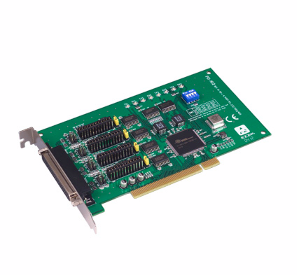
4-port RS-232/422/485 PCI Comm. Card w/S
PCI-1612B-DEMain Features:
- PCI bus specification 2.1 compliant
- Speeds up to 921.6 kbps
- 4-port RS-232/422/485
- 16PCI954 UARTs with 128-byte FIFOs standard
- I/O address automatically assigned by PCI Plug & Play
- OS supported: Windows 98/ME/2000/XP, Linux
- Interrupt status register for increased performance
- Space reserved for termination resistors
- Automatic RS-485 data flow control
- Powerful and easy to use utility (ICOM Tools)
- 2,500 VDC Surge Protection

Frequently Asked Questions
The PCI-1612B is a 4-port PCI communication card. Each port supports RS-232, RS-422, or RS-485, selectable via onboard jumpers.
The PCI-1612B uses a female DB37 connector on the bracket. An optional cable (OPT4A-AE) breaks this out to 4 x male DB9 connectors.
Typical power consumption is 260 mA @ +3.3 V, with a maximum of 530 mA @ +3.3 V.
The operating temperature range is -10 to 60°C (14 to 140°F). Operating humidity is 5-95% RH, non-condensing. Storage temperature is -25 to 85°C (-13 to 185°F).
The card is CE and FCC Class A certified.
The PCI-1612B provides 1000 V surge protection and 15KV (air) / 8KV (contact) ESD protection. Note that the PCI-1612B does not include isolation protection; the PCI-1612C variant adds 3000 VDC isolation protection.
The card supports Windows 7/8/10 and Linux. Refer to the software release note for specific supported OS versions. The included ICOM Tools utility is used for driver setup, port testing, and configuration.
The PCI-1612B measures 174.65 x 106.67 mm (6.88" x 4.2").
The card supports baud rates from 50 bps to 921.6 kbps. Transmission distance is less than 15 m for RS-232 and less than 1000 m for RS-422/485.
Yes. Onboard jumpers (CN5-CN8) allow selection of termination resistors for impedance matching in RS-422/485 mode. Termination resistors should not be set when using RS-232 mode.
How-to Guides
- Install the driver first (see driver setup instructions) before installing the hardware.
- Turn off the computer and all peripheral devices.
- Disconnect the power cord and any other cables from the back of the computer.
- Remove the PC cover.
- Ground yourself by touching the metal chassis of the computer before touching the board.
- Install the PCI-1612B card into an available PCI bus slot.
- Replace the PC cover and reconnect the cables disconnected earlier.
- Turn the computer on. The driver will install automatically.
- Test the COM ports using the ICOM Tools utility to verify normal operation.
- Refer to the pin assignment chart and cabling information when wiring devices.
- Locate the mode-selection jumpers at connectors CN1, CN2, CN3, and CN4 (one connector per channel, CH1-CH4).
- Use a jumper clip to close or open the pins to select the desired mode for each channel.
- The default setting for each channel is RS-232, with Tx Enable Mode set to Auto.
- If configuring RS-422/485, also review the Tx Enable Mode DIP switch (SW2): set to ON for RS-422 Master mode (Tx always enabled), or OFF for RS-422 Slave/RS-485 mode (auto direction control).
- Locate the impedance-selection jumpers at CN5, CN6, CN7, and CN8 (one per channel, CH1-CH4).
- Close the jumper on the corresponding connector to enable the termination resistor for that channel.
- Ensure both ends of the RS-485 bus have termination resistors set for stable communication in electrically noisy environments.
- Do not set termination resistors when operating in RS-232 mode.
- Insert the driver DVD into your drive.
- If AutoPlay does not launch the setup program automatically, run autorun.exe from the DVD using Windows Explorer or the Run command.
- Click Continue on the setup screen, then click Installation to view installation options.
- Choose the driver you want to install and click the corresponding hyperlink.
- To remove the driver later, click Uninstall in the Start Menu folder and follow the prompts.
- Locate the DIP switch SW1 used for setting the board ID.
- Configure switch positions 3, 2, 1, and 0 (BID3-BID0) according to the desired board ID value, using the ON/OFF combinations listed in the Board ID Setting table.
- The default board ID value is 0 (disabled).
- Once COM ports are created, the port number stays linked to the board ID even if the card is moved to a different PCI slot, which helps with maintenance and mass-production identification.
| Manufacturer | Advantech |
|---|