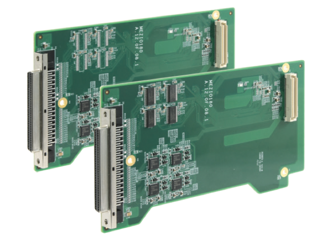
MezIO-C181: 4 x RS-232/422/485 and 4 x RS-422/485 Ports
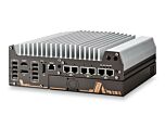
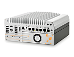
MezIO-C181Works with POC-300, Nuvo-5000 Series, and the Nuvo-7000 Series Platforms from Neousys
Main Features:
- 4x RS-422/485 ports
- Up to 921.6 Kbps baud rate
- BIOS-configurable mode/termination
- Supports Windows 7/8/8.1/10
- SCSI-II 68-pin connector

Frequently Asked Questions
The MezIO-C181 provides 8 serial ports total: 4 ports that are switchable between RS-232/422/485 mode, and 4 fixed RS-422/485 ports. This differs from the MezIO-C180, which has 4 switchable RS-232/422/485 ports plus 4 fixed RS-232 ports.
The MezIO-C181 supports baud rates from 50 bps up to 921,600 bps (921.6 Kbps) on all ports.
The module uses a 68-pin SCSI-II female connector to carry all 8 serial channels. A breakout cable (Cbl-S68M-8DB9M-50CM, SCSI-68 male to 8x DB-9 male, 50 cm) is available to split this into individual DB-9 connectors.
The MezIO-C181 supports Windows 7, 8, 8.1, and 10, as well as Linux kernel 2.6.32 or later.
The product datasheet lists 8 kV ESD protection for the MezIO-C181's serial ports.
Depending on the mode selected for a given port, the following signals are available:
- RS-232: TxD, RxD, RTS, CTS, DTR, DSR, DCD, GND
- RS-422: TxD+, TxD-, RxD+, RxD-, GND
- RS-485: Data+, Data-, GND
Yes, each port has a 256-byte TX and RX FIFO.
The MezIO-C181-50 is for Nuvo-7000, Nuvo-5000, POC-500, and POC-300 series hosts. The MezIO-C181-12 is for the POC-120 series.
Yes. The mode and termination settings for each port are BIOS-configurable, as stated in the product's key features.
How-to Guides
- Identify which of the 4 switchable UART ports (UART0-UART3) you want to use in RS-232 mode; ports UART4-UART7 on the MezIO-C181 are fixed RS-422/485 and do not support RS-232.
- Set the desired port to RS-232 mode in BIOS.
- Use the SCSI-68 breakout cable (or a DB-9 device connector) to access the RS-232 signals: DCD, RxD, TxD, DTR, GND, DSR, RTS, CTS as defined in the DB9 connector pin-out table.
- Connect the RS-232 device's TxD to the module's RxD, RxD to the module's TxD, and GND to GND, plus any handshaking lines (RTS/CTS, DTR/DSR, DCD) your device requires.
- Select a UART port and set it to RS-422 mode in BIOS.
- Reference the RS-422 pin-out of the DB9 device connector: pin 2 = 422 TXD+, pin 3 = 422 RXD+, pin 4 = 422 RXD-, pin 5 = GND, pin 8 = 422 TXD-.
- Connect the RS-422 device's differential receive pair to the module's TXD+/TXD- lines, and the device's differential transmit pair to the module's RXD+/RXD- lines.
- Connect GND between the module and the device.
- Select a UART port and set it to RS-485 mode in BIOS.
- Reference the RS-485 pin-out of the DB9 device connector: pin 2 = 485 TXD+/RXD+, pin 8 = 485 TXD-/RXD-, pin 5 = GND.
- Connect the module's Data+ line to the RS-485 bus's Data+ line, and Data- to Data-.
- Connect GND between the module and the RS-485 network.