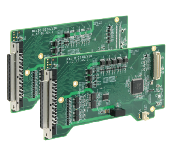
MezIO-D220 - 8-CH isolated digital input and 8-CH digital isolated output via 68 pin SCSI connector
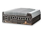
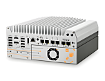
MezIO-D220Works with POC-300, Nuvo-5000 Series, and the Nuvo-7000 Series Platforms from Neousys
Main Features:
- 8-CH isolated DI
- 8-CH isolated DO
- 2500 Vrms isolation voltage
- Up to 24 VDC operation for DI and DO
- Up to 500 mA sink current on DO channel
- SCSI-II 68-pin connector

Frequently Asked Questions
The MezIO-D220 provides 8 channels of isolated digital input (DI) and 8 channels of isolated digital output (DO).
The product datasheet lists an isolation voltage of 2500 Vrms for both DI and DO. The MezIO technical reference guide lists a rating of 3750 Vrms for the same channels. Confirm the exact rating with Neousys documentation for your specific revision before specifying in a high-isolation application.
Logic high is 5 to 24 VDC and logic low is 0 to 1.5 VDC (listed in the datasheet as 5 to 1.5 VDC in the technical guide). Rated and maximum input voltage is 24 VDC. The DI interface uses a unipolar photo-coupler and supports polling and change-of-state (COS) operation modes.
Each DO channel can sink up to 500 mA at 100% duty cycle. Operating voltage is up to 24 VDC, with a maximum driving voltage of 30 VDC. The DO stage uses a MOSFET, open-drain interface configured as normally open (NO).
Yes. On the MezIO-D220, digital input channels 0 through 7 support both sink (NPN) and source (PNP) wiring configurations, and each channel wires individually.
The MezIO-D220 uses a 68-pin SCSI-II female connector for its I/O interface.
The MezIO-D220-50 variant is for Nuvo-7000, Nuvo-5000, POC-500, and POC-300 series systems. The MezIO-D220-12 variant is for the POC-120 series.
Neousys offers the Cbl-S68M-S68M-100CM (SCSI-68 male to SCSI-68 male cable, 100 cm) and the TB-10 terminal board, which has a 68-pin SCSI-II female connector and a 68-pole terminal block for easier field wiring.
Yes. The module provides an isolated 5V output with a rated driving current of 100 mA. This 5V rail is intended only to supply the internal DO chipset and should not be used to drive external devices.
Neousys provides a DIO API with functions including InitDIO(), DIReadLine(), DIReadPort(), DOWriteLine(), DOWritePort(), DOWriteLineChecked(), and DOWritePortChecked() for controlling isolated digital I/O on MezIO-D220/D230 modules.
How-to Guides
- Identify whether you want to use sink (NPN) or source (PNP) wiring; channels 0 to 7 on the MezIO-D220 support either, wired individually per channel.
- Supply 5 to 24 VDC to the input to represent a logic high state, or 0 to 1.5 VDC to represent a logic low state.
- Connect the return path through the corresponding DIGND pin as documented in the MezIO-D220 pin-out table.
- Do not exceed the maximum input voltage of 24 VDC.
- Note that the DO channels are configured as normally-open (NO); on power-up all channels default to logic 0, meaning the circuit is disconnected from the GND return.
- To activate a channel, write logic 1 to enable the internal MOSFET and establish the GND return path (sinking current connection).
- Keep the driving current at or below 500 mA per channel (100% duty) and the driving voltage at or below 30 VDC.
- Connect the load between the DO pin and the appropriate DOGND pin per the MezIO-D220 pin-out table. A protection diode across the DO channel and VDD is already implemented internally to suppress voltage spikes from inductive loads or long wiring runs.
- Call
InitDIO()once before performing any DIO read/write operations; it returns TRUE if initialization succeeds. - To read a single input channel, call
DIReadLine(ch), wherechis the channel number. - To read all 8 input channels at once, call
DIReadPort(), which returns a value from 0 to 255. - To write a single output channel, call
DOWriteLine(ch, value), or useDOWriteLineChecked(ch, value)if you want the function to block until the register write is confirmed. - To write all 8 output channels at once, call
DOWritePort(value)orDOWritePortChecked(value)for a confirmed write.
- Refer to the MezIO-D220 pin-out table to locate DI0H-DI7H/DI0L-DI7L pairs and their corresponding DIGND pins.
- Locate DO0-DO7 output pins and their corresponding DOGND pins, along with the VDD and ISO5V pins.
- Use the TB-10 terminal board accessory, which breaks out the 68-pin SCSI-II connector to a terminal block, to simplify field wiring instead of soldering directly to the SCSI connector.